
Two Days From Idea to a Working Lightning Detector
A board like this used to take me weeks. This one took two days.
Solderable teamed up with Embedder to see how fast the two of us could ship working hardware. My side covers the board, from part selection through to layout. Firmware is Embedder's half, from an empty repository to a finished interface.
What came out is Storm Tracker, a handheld lightning detector that clips to a pack, runs for months on one charge, and beeps when a storm starts to move in. Everything on it had to be real: a case, a battery, a screen, and bare chips throughout.
I design hardware and firmware for a living, mostly low-power IoT and FPV drones, so a device that sits in a rucksack all season without a charge is a good excuse to argue with myself about microamps. I also hike, which is where the idea came from. Weather above the treeline turns over fast and my phone has no signal, so a radar map does me no good on an exposed ridge.
The board is open. Everything shown in these photos, the KiCad project, the schematic, the full BOM, and the files a factory needs, is at solderable/storm-tracker-hardware. Open it alongside this post if you want to see any decision below in the actual design.
The first three of those ran inside Solderable, and they ran asynchronously. I started part selection and went off to do other things while it worked in the background. The design review went the same way. My hands were only needed for the decisions, so machine time and my time overlapped for most of that first block.
Contents
- What it is
- The 500 kHz problem
- The screen that fights the sensor
- Battery life and powering off
- Designing the board
- Half a day of firmware
- The first real storm
- Taking it up Wedgemount
- What Solderable does
What it is
Storm Tracker is a handheld lightning detector. The body is a small brick, close in shape to a Garmin eTrex. It has an e-paper screen, three buttons on the front, a power button on the side, and a USB-C port.
The screen gives me a count of strikes and the distance to the storm. The buzzer is loud enough to hear through a zipped pack lid.
I set one rule for the build. Every part had to be a bare chip on a board I laid out myself. Breakout boards and drop-in modules were out. I made a single exception for the radio, because a pre-certified module keeps the regulatory work simple.
The 500 kHz problem
One part shaped the board: the ScioSense AS3935.
Lightning radiates a broadband radio burst called a sferic, and it carries for hundreds of kilometres. The AS3935 listens for sferics on a tuned loop antenna, measures the shape of the pulse envelope, and decides whether it heard a flash or a washing machine. It reaches 40 km and reports distance to the head of the storm in 15 steps. Listening costs about 60 µA.
One sensor gives distance and no bearing, so the screen shows a number and a trend. That covers the question I ask on a ridge.
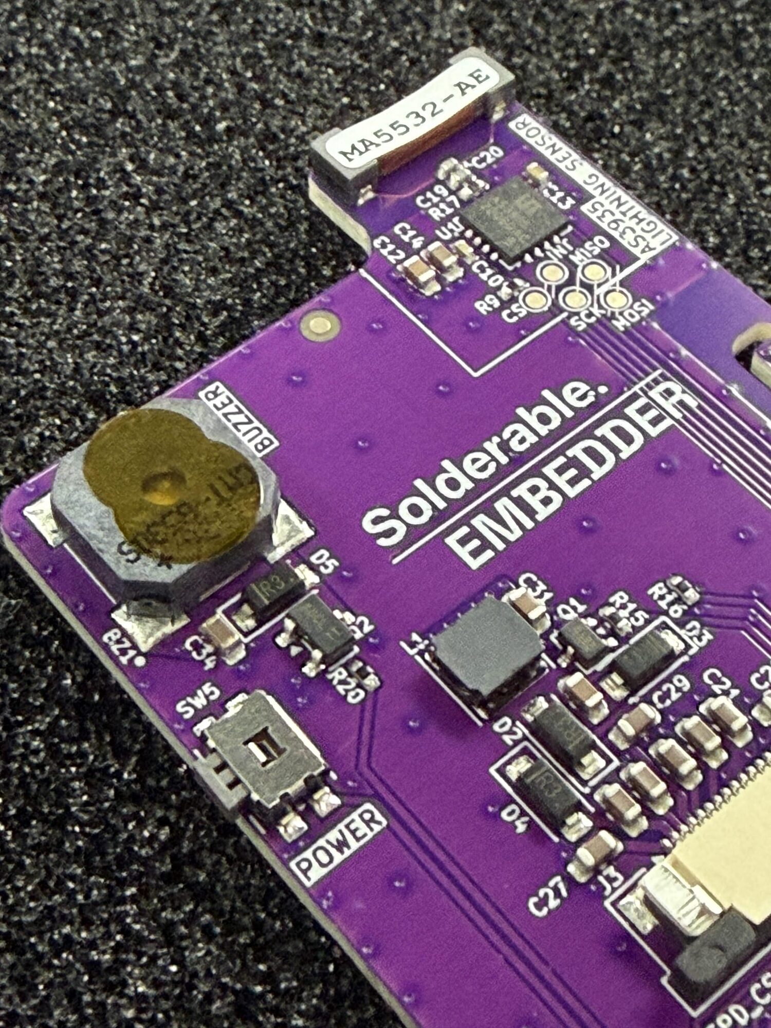
The coil is the labelled brick at the top edge, and the chip is the small square below it. It is a Coilcraft MA5532, tuned against 680 pF and 270 pF C0G capacitors with a 10 kΩ damping resistor across it.
That coil is tuned to 500 kHz, and the number drove most of my hardware decisions. Any noise the board makes near 500 kHz looks like lightning to the chip.
Nothing on this board switches continuously. A buck converter running at a few hundred kilohertz would push its harmonics straight into the sensor passband, so power comes from a TLV75533 LDO at 3.3 V drawing 25 µA idle. An LDO wastes the voltage difference as heat, and I paid that for a quiet board. SPI runs at 1 to 2 MHz for the same reason.
The antenna also needs clear space beneath it, since eddy currents in a ground plane pull a resonant loop off tune and damp it. The board is notched away around the coil, with the copper removed on all four layers and the AS3935 sitting at the base of that tab. The plastic bump on the case keeps conductive material away from it.
The screen that fights the sensor
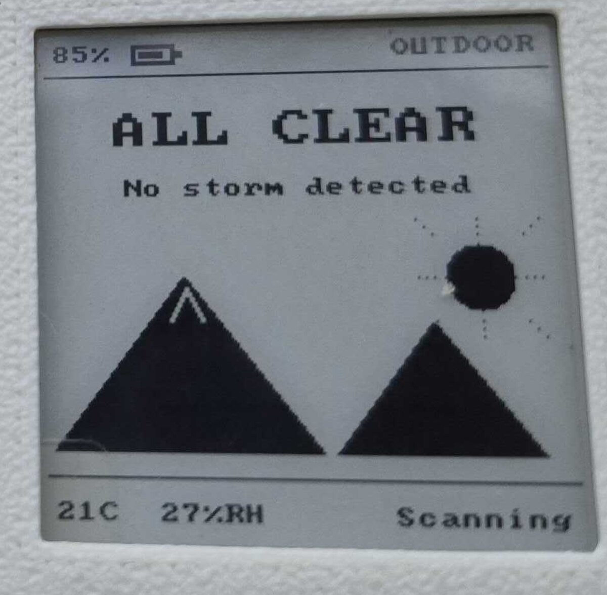
The screen is a Good Display GDEY0154D67: a 1.54 inch e-paper panel, 200 by 200 pixels, on an SSD1681 controller.
E-paper holds an image with no power at all. My device spends most of its life showing ALL CLEAR, sometimes for weeks, and the screen costs me nothing while it does. The trade is speed, since a refresh takes about a second and a half. I glance at this device rather than browse it, so I can live with that.
The awkward part is that e-paper needs high voltage to flip the ink, and the panel does not make it. The panel controller drives a boost converter that I have to build on my own board. So the screen forced a switching converter onto the one board where I had banned switching converters.
Timing gets around it. The boost only runs during a refresh, so the firmware puts the AS3935 to sleep first, updates the screen, and wakes the sensor once the panel reports that it has finished. My device goes deaf for a second and a half, a few times an hour. A storm covers very little ground in that window.
The panel also refreshes only between 0 and 50 °C. Below freezing the controller finds no matching waveform table and gives up silently, leaving the last image on screen. The AS3935 keeps working down to -40 °C, so in deep cold the device still knows a storm is coming and says so through the buzzer. The firmware checks panel temperature before every refresh and skips the update when the reading sits outside the window.
Battery life and powering off
Idle current decides whether this thing is worth carrying. This is where it goes:
The sensor draws more than everything else combined. The supporting parts stay out of its way. At 98 µA a small 1S LiPo pouch lasts months. A two-week trip spends a few percent of the pack.
For power management I used a TI BQ25186, an I²C charger with the input and battery FETs built in. It is also stocked at LCSC as C44639442 if your assembler sources from there. The feature I care about is Ship Mode. A long press on the side button tells the chip to open the battery FET and cut the whole downstream rail, and draw falls to about 3 µA.
That long-press logic lives inside the charger itself, on its TS/MR pin. It still works when my firmware has locked up, which is exactly when I want a power button to obey me. The same button brings the device back, and so does plugging in USB.
The button is a Panasonic EVQPUD02K, side-actuated so it presses through the wall of the case. I posted a clip of it clicking and that clip has done better numbers than anything else I have put on the internet.
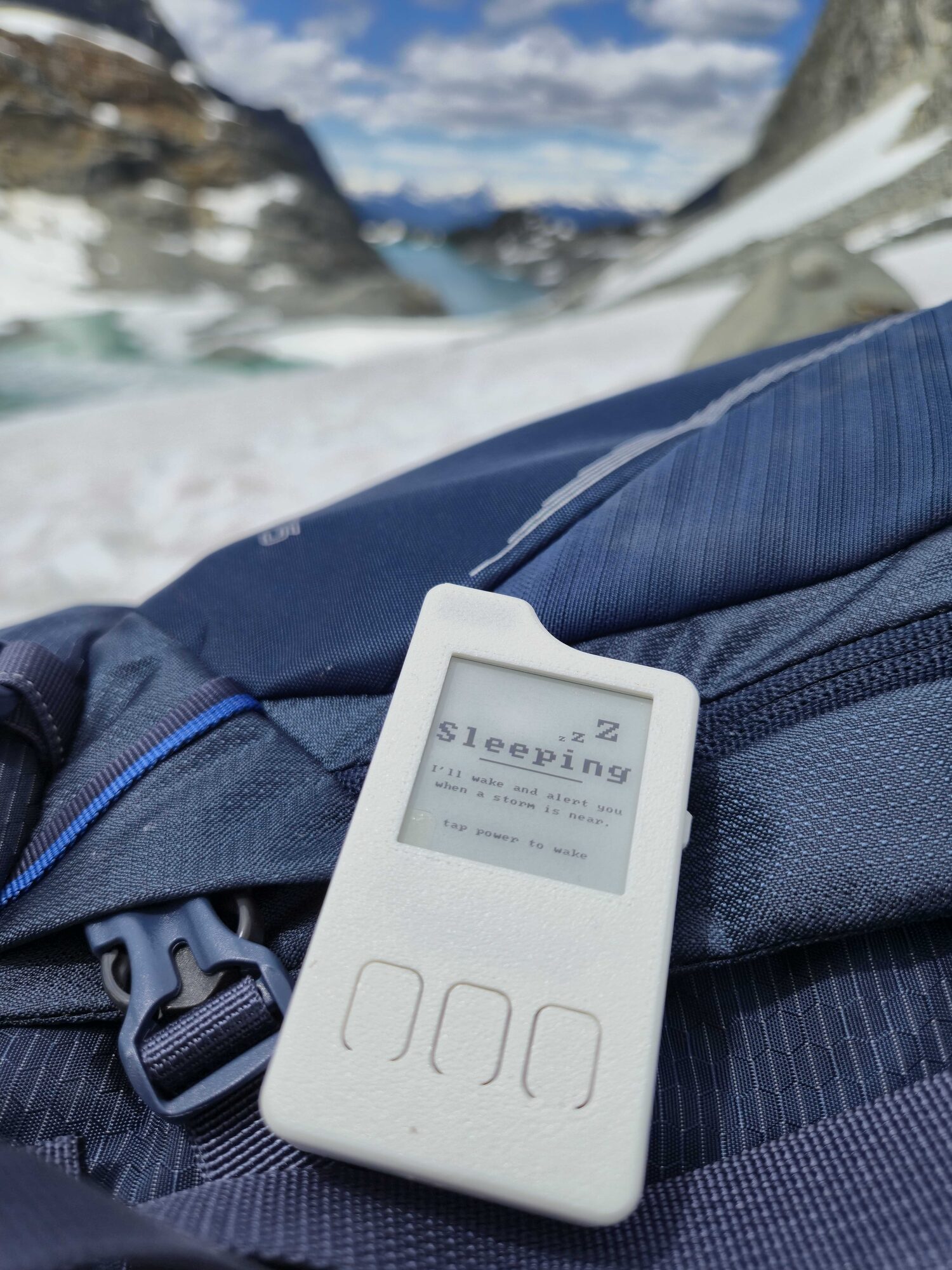
Just before the rail dies, the firmware writes one last frame: Sleeping. I'll wake and alert you when a storm is near. Tap power to wake. Then the power goes away and the message sits there at zero current for as long as it needs to.
Designing the board
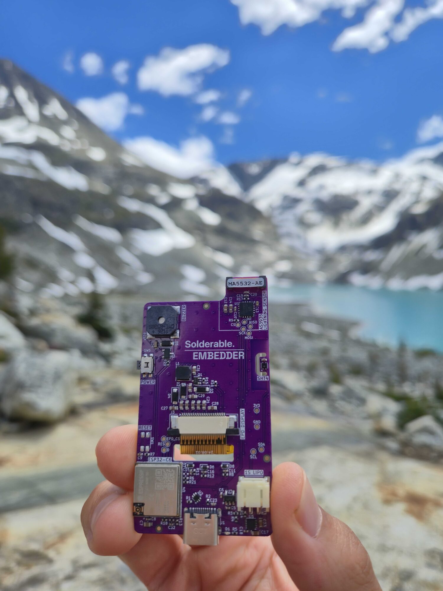
Two and a half hours covered part selection, the schematic, and the design review. Layout took another four, done by hand. I would like to automate more of that step later.
The board is about 35 by 75 mm, four layers, 1.0 mm thick. Thin suits a slim body, and 1.0 mm sits close to the structural floor for this size once it gets squeezed inside a pack.
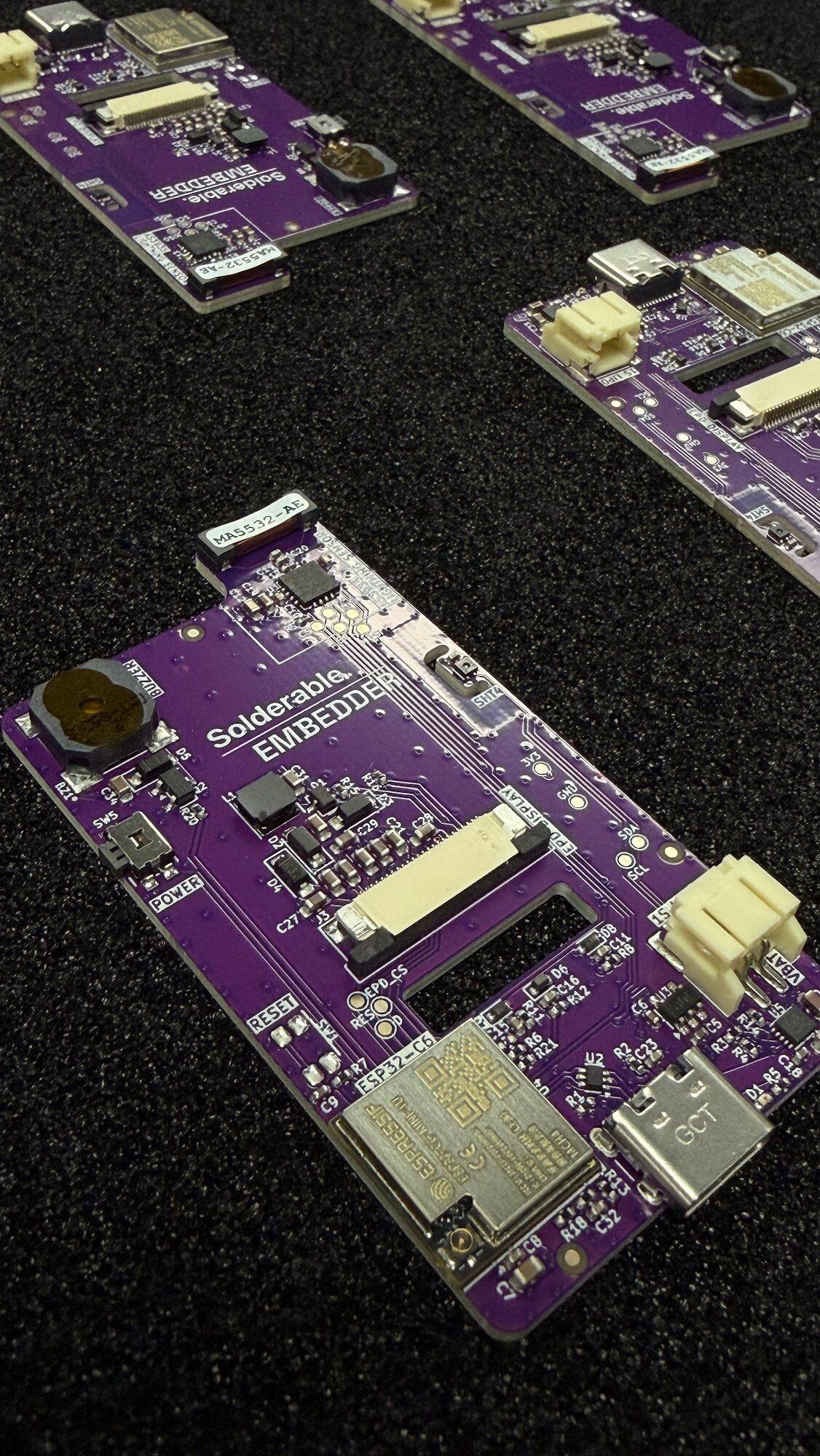
The front face carries the display and the three buttons. Everything else lives on the back: processor, charger, boost converter, sensor, buzzer, USB-C, battery connector. A clean front was part of the reason, and cost was the larger part. With the parts on one side, the assembly house populates a single face, I hand-solder the three front switches myself, and I pay for one pass through the line.
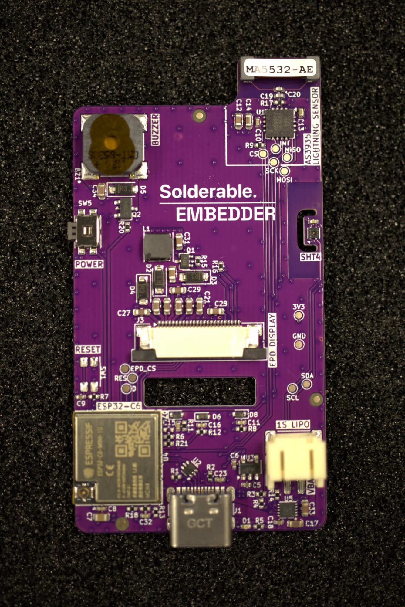
The display connects through a slot cut in the middle of the board. I rotated the panel 90° so the flex tail exits the bottom, passes through the slot, and folds 180° onto a connector on the back face. Only 14 mm of that tail is free, which forces the connector to within about 5 mm of the slot with its mouth pointed at it. I rounded the slot edge so the fold gets a real bend radius, and bonded the panel for strain relief. The panel must never be plugged or unplugged with power applied.
Six and a half hours is fast, and most of the thinking was finished before I opened the layout tool. The 500 kHz rule had already removed whole classes of power topology. The reference circuits for the boost converter and the charger come out of the datasheets and are worth copying component for component. My mechanical envelope was fixed.
Half a day of firmware
Embedder wrote the firmware, which was their half of the experiment. I handed over the KiCad schematic, the project files, and a page describing what the device does.
My first instruction was to test every part on its own before writing any product code. Embedder pulled the datasheets, read the schematic to work out the wiring, and went through the board piece by piece:
- talk to the charger over I²C
- read the Sensirion SHT4x temperature and humidity sensor
- bring up SPI to the AS3935
- push a frame to the panel
- drive the CMT-8530S buzzer
The ESP32-C6 module earned its keep here. USB-Serial-JTAG is built into the chip. One USB-C cable does the flashing and the debugging, and carries the serial log. It needs no external debugger, and the bootloader opens without a button press. A code change gets to running hardware without anybody touching the device. Embedder ran that cycle on real boards while I worked on the enclosure.
A few details in bring-up will eat an afternoon if you get them wrong:
- Antenna calibration. Component tolerance leaves every AS3935 antenna a little off resonance, and the chip forgets its tuning on every power cycle. At each cold boot the firmware turns on the LCO output on the interrupt pin. It then sweeps the internal tuning capacitor through its 16 settings while it measures frequency, keeps the best one, and runs the RCO calibration command. Every board tunes itself.
- The 2 ms wait. After the interrupt pin rises, the firmware waits 2 ms before it reads the register that holds the interrupt source. An early read returns garbage.
- Charge current. The register that sets charge current in the BQ25186 powers up at 10 mA. Leave it alone and your battery charges at a trickle while everybody wonders why. The firmware writes it at boot, along with the undervoltage cutoff and the settings for the Ship Mode button.
- Radio off. Wi-Fi transmit peaks near 350 mA, which loads the LDO hard and wrecks the idle budget. The radio stays off until I ask for it.
Once every part answered on its own, we went into plan mode and designed the user interface together. Embedder then produced the firmware in a single pass. Everything after that was cosmetic: font sizes, and where the lightning glyph sits.
The first real storm
The first storm it caught arrived while the board was still bare on my desk, so I filmed it from the window.
The screen reads one kilometre to the storm front, with tens of strikes an hour and the last one a few seconds old. You can also watch the panel invert to black and back partway through, which is how e-paper clears an old image before it draws the new one.
Testing a lightning detector on a bench is awkward. The usual trick is a piezo spark igniter. It puts out something close enough to a sferic to trip the sensor, and it tells me nothing about accuracy at range or how the filter copes with real noise, which only weather can show me.
Taking it up Wedgemount
The field trip was Wedgemount Lake and Tupper Lake, in Garibaldi Provincial Park north of Whistler.
The numbers describe this trail better than I can. It gains around 1200 m in 7 km one way. Trailforks rates it black diamond with an extreme physical rating, and the four thousand-odd AllTrails reviews mostly say the same thing in different words: almost none of it is flat. The grade never lets up through the forest, and the final kilometre turns into a boulder scramble where your hands come off your poles and onto the rock. Several reviews warn that the last 45 minutes get loose and slippery when wet.
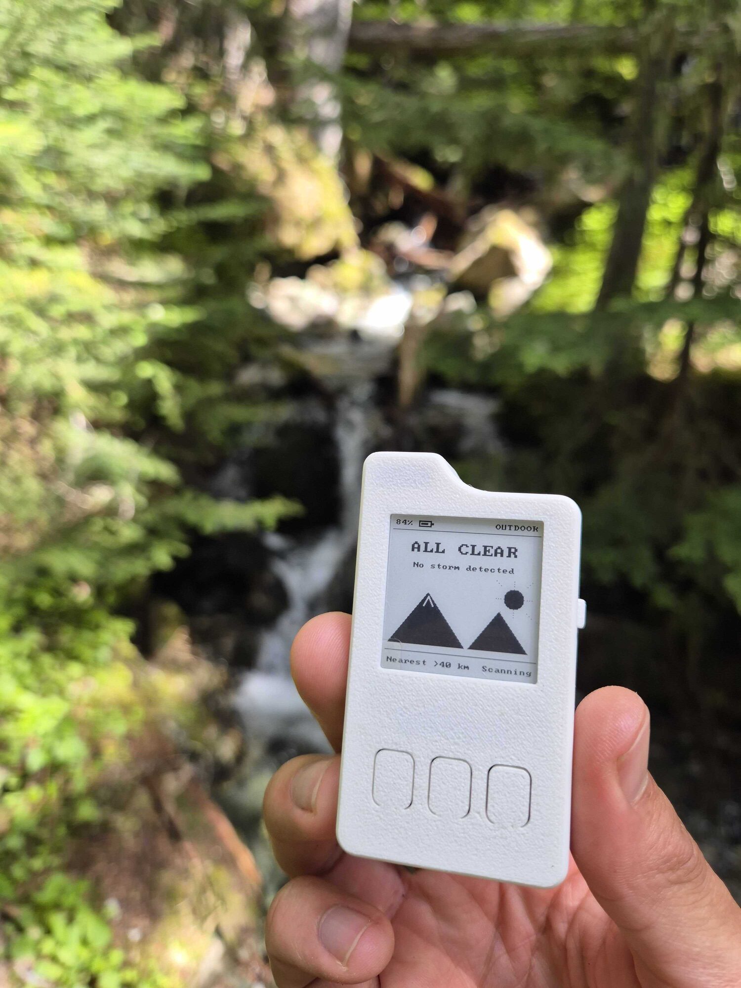
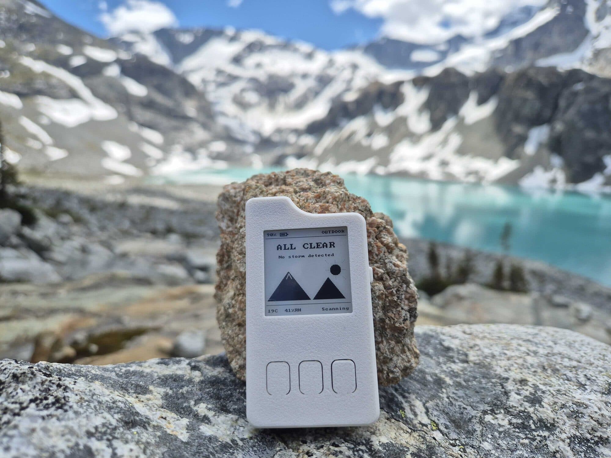
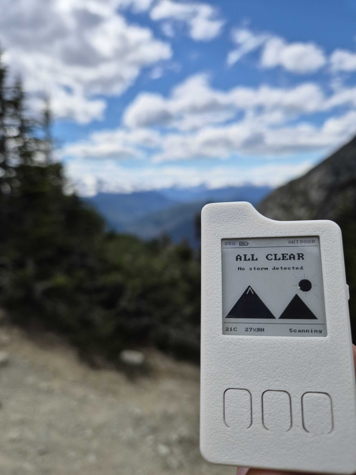
That photo is from the forest section, where most of the climbing happens and nothing is visible except trees and water. The device rode on my shoulder strap and read Nearest >40 km, Scanning the whole way up.
I went early enough in the season that snow was still lying on the upper slopes, so I carried an axe.
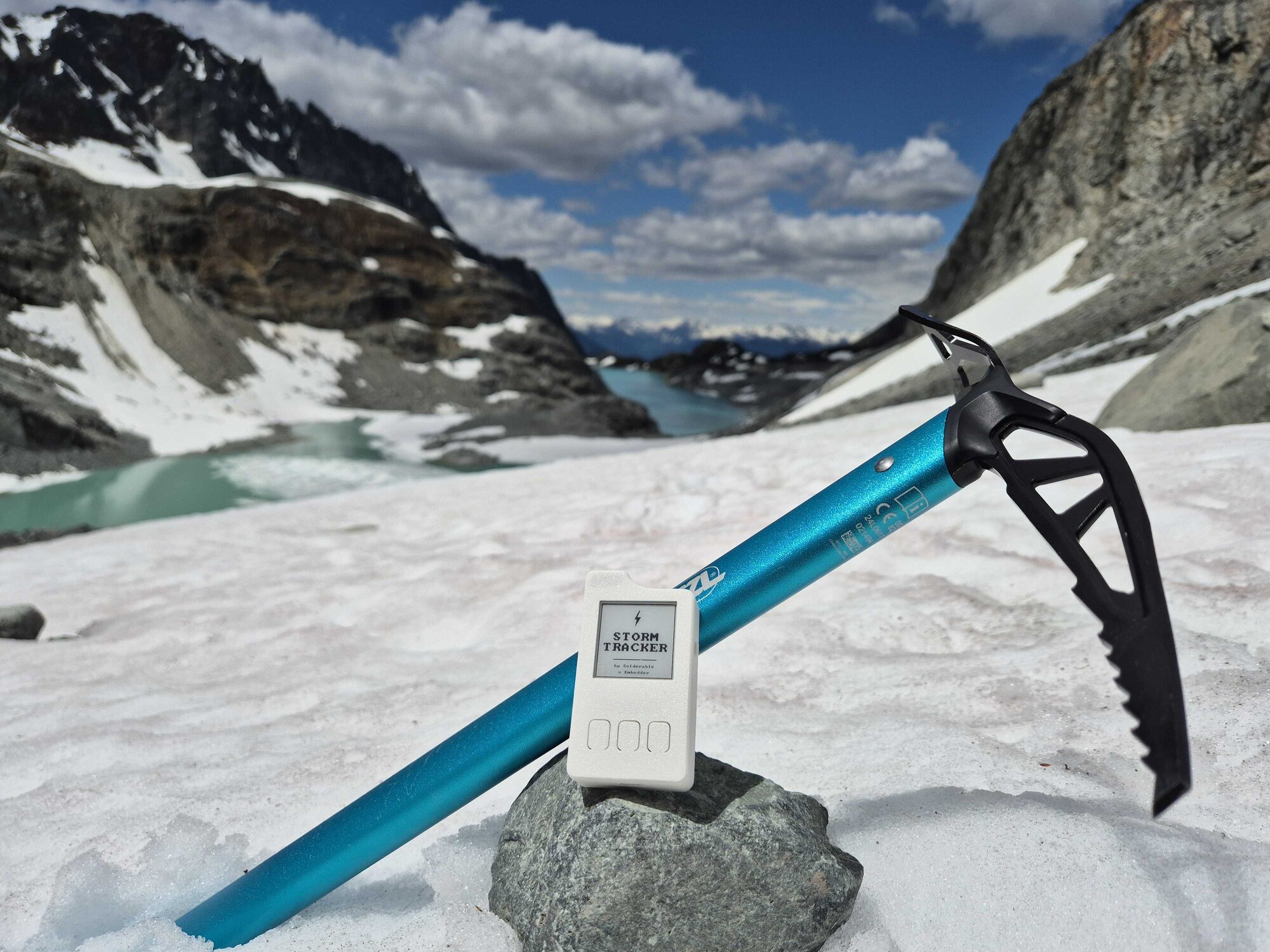
Above the boulder field the lake opens up all at once. The colour is rock flour ground off by the glacier above it, suspended in the meltwater, and no camera setting is doing that.
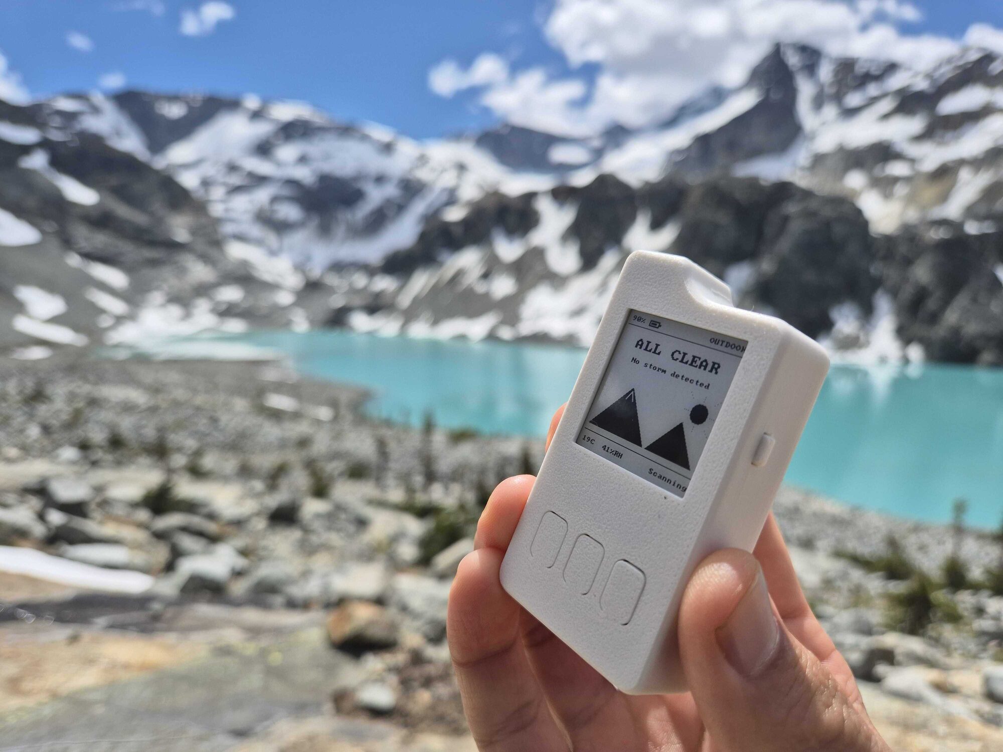
BC Parks keeps 20 tent pads up there on wooden platforms built straight into the boulders, since there is no flat ground otherwise. A hut sits on the ridge above the lake. The BC Mountaineering Club put it up in 1970, it sleeps about eight, and it is now reserved for emergencies. You need a booking year-round to camp.
Nothing happened for two days, which is the correct outcome and a strange thing to photograph. The screen sat at ALL CLEAR, 19 °C, 41% humidity, scanning, and the battery moved from 90% to 84%. I stopped checking the sky every ten minutes.
What Solderable does
We design boards for clients, and speed is the point. Storm Tracker took six and a half hours of board work, from an empty project through to a layout ready for fabrication. Client projects run the same way.
A lot of that speed comes from work that does not need me sitting in front of it. I describe what the board has to do and get on with something else while part selection and the design review come back. My hands are needed for the decisions and nothing else.
Most projects reach us stuck somewhere between a design that looks finished in CAD and a package a manufacturer will accept. We pick it up wherever it stalled: part selection, schematic, layout, manufacturing files, BOM and supplier work, and DFM feedback from the factory.
The whole Rev A package that came out of that process is public at solderable/storm-tracker-hardware: KiCad source, schematic PDFs, BOM, and order-ready gerbers for the exact boards in these photos. It is hobby hardware, so treat it as a second opinion on a ridge rather than a forecast.
If you have a board that needs designing, book a call.
More from the workbench.
All articles